- 您现在的位置:买卖IC网 > Sheet目录989 > MAX16840EVKIT+ (Maxim Integrated Products)KIT EVAL FOR MAX16840 LED DVR
�� �
�
�MAX16840�
�LED� Driver� with� Integrated� MOSFET�
�for� MR16� and� Other� 12V� AC� Input� Lamps�
�Boost� Diode� (D1)�
�A� Schottky� diode� must� be� used� as� rectifier� diode� D1� to�
�reduce� power� dissipation.� The� voltage� rating� of� diode�
�D1� must� be� greater� than� the� maximum� output� voltage.�
�Choose� a� diode� that� minimizes� dissipation� at� tempera-�
�tures� in� the� +90� N� to� +100� N� C� range.� The� diode� should� be�
�selected� to� minimize� reverse� leakage� at� the� maximum�
�output� voltage� while� minimizing� forward� losses� when� the�
�diode� is� conducting.�
�Loop� Compensation� (R2,� C4)�
�The� crossover� frequency� of� the� loop� must� be� maximized�
�to� get� the� optimum� performance.� The� maximum� value� of�
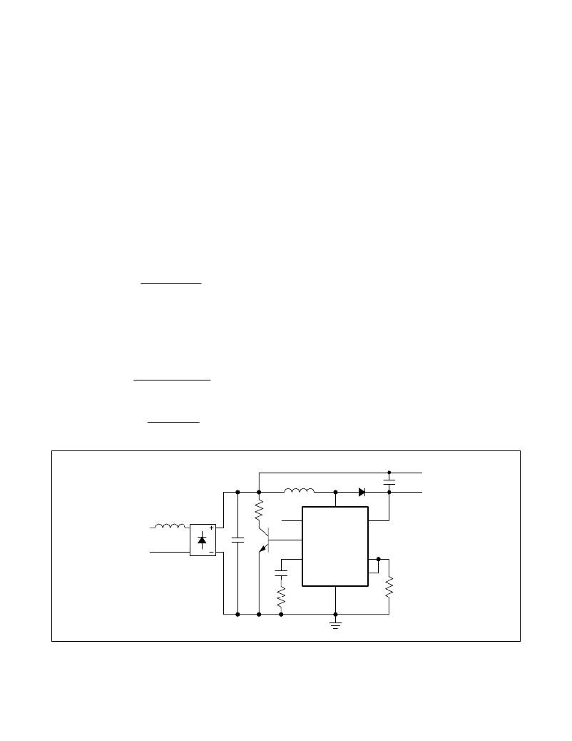
�Buck-Boost� Configuration�
�In� MR16� applications,� the� buck-boost� configuration� is�
�used� when� the� number� of� LEDs� is� in� the� 3-to-5� LED�
�range.� Figure� 3� shows� the� schematic� of� a� buck-boost�
�LED� driver.� The� maximum� voltage� on� LED+� should� not�
�exceed� 40V.�
�Resistor� (R1)�
�If� the� desired� maximum� output� power� with� 12V� AC� at�
�50Hz� or� 60Hz� is� P� OUT� ,� the� input� power� P� IN� is� given:�
�P� IN� =� P� OUT� /� n�
�where� n� is� the� efficiency.� The� input� current� is� given� by:�
�R2� is� given� by:�
�R2� MAX� =�
�2� � 300kHz� � L2�
�R1� � V� LED� � g� m�
�in� k� ?�
�I� IN� =� P� IN� /12V�
�The� resistor� R1� is� then� given� by:�
�R1� =� 0.2V/I� IN�
�where� R1� is� in� ohms,� V� LED� is� in� volts,� g� m� is� the� transcon-�
�ductance� of� the� error� amplifier� in� F� S,� and� the� value� of�
�the� inductor� L2� is� in� F� H.� Choose� a� value� of� R2� 20%� lower�
�than� the� above� value.�
�The� zero� from� C4,� R2� should� be� placed� at:�
�where� R1� is� in� ohms� and� I� IN� is� in� amps.�
�Buck-Boost� Inductor� (L2)�
�For� optimum� efficiency,� the� inductor� must� be� operating�
�in� continuous-conduction� mode.� The� maximum� peak�
�current� in� the� inductor� occurs� at� the� peak� of� the� highest�
�fz� =�
�R1� � V� LED� � g� m� � R2�
�12V� ×� π� ×� L�
�input� voltage.� The� P-P� ripple� at� this� input� voltage� is� D� I� L� .�
�The� maximum� input� current� occurs� at� the� highest� input�
�voltage.� Typically,� the� highest� input� voltage� is� 13.2V� AC,�
�Therefore,� C4� is� given� by:�
�which� is� 10%� higher� than� the� typical� value.�
�C4� =�
�1�
�2� ×� π� ×� fz� ×� R2�
�The� peak� current� in� the� inductor� is:�
�I� PK� =� I� INDMIN� +� 0.5?I� L�
�LED-�
�L2�
�D1�
�C2�
�LED+�
�L1�
�BD1�
�R3�
�REFI�
�DRAIN�
�IN�
�12V� AC�
�C1�
�EXT�
�COMP�
�MAX16840�
�SOURCE�
�C4�
�GND�
�FB�
�R1�
�R2�
�Figure� 3.� Buck-Boost� LED� Driver�
�10�
�Maxim� Integrated�
�发布紧急采购,3分钟左右您将得到回复。
相关PDF资料
MAX16841EVKIT+
WIDE INPUT OFFLINE LED DRIVER
MAX19515EVKIT+
KIT EVAL FOR MAX19515 ADC
MAX44000EVKIT#
KIT EVAL FOR MAX44000
MAX5312EVKIT+
KIT EVAL FOR MAX5312
MAX5550EVKIT+
KIT EVAL FOR MAX5550
MAX5891EVKIT#
KIT EVALUATION FOR MAX5891
MAX6629EVKIT
EVAL KIT FOR MAX6629
MAX6635EVKIT+
EVALUATION KIT FOR MAX6635
相关代理商/技术参数
MAX16841ASA+
功能描述:LED照明驱动器 Wide Input Offline w/Dimming
RoHS:否 制造商:STMicroelectronics 输入电压:11.5 V to 23 V 工作频率: 最大电源电流:1.7 mA 输出电流: 最大工作温度: 安装风格:SMD/SMT 封装 / 箱体:SO-16N
MAX16841ASA+T
功能描述:LED照明驱动器 Wide Input Offline w/Dimming
RoHS:否 制造商:STMicroelectronics 输入电压:11.5 V to 23 V 工作频率: 最大电源电流:1.7 mA 输出电流: 最大工作温度: 安装风格:SMD/SMT 封装 / 箱体:SO-16N
MAX16841BEVKIT#
功能描述:LED 照明开发工具 RoHS:否 制造商:Fairchild Semiconductor 产品:Evaluation Kits 用于:FL7732 核心: 电源电压:120V 系列: 封装:
MAX16841EVKIT#
功能描述:LED 照明开发工具 MAX16841 Eval Kit
RoHS:否 制造商:Fairchild Semiconductor 产品:Evaluation Kits 用于:FL7732 核心: 电源电压:120V 系列: 封装:
MAX16841EVKIT+
功能描述:LED 照明开发工具 MAX16841 Eval Kit
RoHS:否 制造商:Fairchild Semiconductor 产品:Evaluation Kits 用于:FL7732 核心: 电源电压:120V 系列: 封装:
MAX16842ASA+
功能描述:模数转换器 - ADC New RoHS:否 制造商:Texas Instruments 通道数量:2 结构:Sigma-Delta 转换速率:125 SPs to 8 KSPs 分辨率:24 bit 输入类型:Differential 信噪比:107 dB 接口类型:SPI 工作电源电压:1.7 V to 3.6 V, 2.7 V to 5.25 V 最大工作温度:+ 85 C 安装风格:SMD/SMT 封装 / 箱体:VQFN-32
MAX16842ASA+T
功能描述:模数转换器 - ADC New RoHS:否 制造商:Texas Instruments 通道数量:2 结构:Sigma-Delta 转换速率:125 SPs to 8 KSPs 分辨率:24 bit 输入类型:Differential 信噪比:107 dB 接口类型:SPI 工作电源电压:1.7 V to 3.6 V, 2.7 V to 5.25 V 最大工作温度:+ 85 C 安装风格:SMD/SMT 封装 / 箱体:VQFN-32
MAX1684EEE
功能描述:直流/直流开关转换器 14V 1A PWM Step-Down Converter RoHS:否 制造商:STMicroelectronics 最大输入电压:4.5 V 开关频率:1.5 MHz 输出电压:4.6 V 输出电流:250 mA 输出端数量:2 最大工作温度:+ 85 C 安装风格:SMD/SMT